IRDMT PRACTICAL WORKBOOK

Disclaimer:
These notes are my personal digital compilation, created for learning and teaching purposes. You are free to use them for study, reference, or instructional use. However, they may contain unintentional errors or omissions. I do not take responsibility for any inaccuracies, so readers are advised to cross-check and verify the content independently.
MAINLY WE HAVE
SAFETY
- PPE
- Safety Signs Identification FOR Danger , Warning ,caution and personal safety message.
- Fire Extinguisher Types and Usage
- first aid kit , when to use what.
- Listing Each Robot Components , Identification & Functions ,tools , machinery
- Teach Pendant Buttons - EACH BUTTON USAGE - types of keys
- Types of Coordinate Systems ,,
- cartesian ,
- Joint ,
- user ,
- tool etc..,
- Identification of X, Y, Z & (S, L, U, R, B, T) by Jogging ,,robot moment
- Jogging with Pendant USING AXIS KEYS
- CO-ordinate system , Jogging with Rectangular , joint co-ordinate system.
- Basic Program Structure , syntax etc..,
- Work Object Definition & Motions (MOVJ, MOVL, MOVC – Interpolation)
- MOVJ Operation
- MOVL Operation
- MOVC OperationCombined Motion (MOVL + MOVC)
- MOVS Operation
- Gripper , conveyor belts and their working mechanisms
- Handling instructions , informlist (options exploring )dout etc..
- handling operations - dout, pulse setting etcc..
- Pick and Place with Pendant ,
- shift Instructions
- Advanced Loop Instructions
- Arc welding , Architecture ,,block diagram
- working of c0 2 gas , welding gun , table , earthing etc..,
- Welding Program Structure (ARCON, ARCOFF, WAVON, WAVOFF) n different shapes , T -JOINT WELDING
- Welding using Teach pendant .
- welding parameter settings , weld quality , Adjusting Voltage , current etc..,
- Types of Alarms and resolutions
- Preventive Maintenance (Oiling, Lubrication, Cleaning, etc.) planning and conducting
- Industry 4.0 & Remote Monitoring
- Intro to simulation
- Jogging in MotoSim
- Welding in MotoSim
- pick and place in motosim


Safety attitude development of the trainee by educating them to use Personal Protective Equipment (PPE)...✅

TITLE / AIM
To learn correct use of Personal Protective Equipment (PPE) for safety.
OBJECTIVES
Learn how to wear PPE correctly.
Know the importance of PPE for safety.
TOOLS REQUIRED
Hard hat
Safety goggles
Safety gloves
Safety shoes
Safety apron
MATERIAL REQUIRED
PPE kit – 1 set
Cleaning cloth – 1
EQUIPMENT REQUIRED
Workshop area
Safety instruction chart
SEQUENCE OF OPERATION
Select correct PPE
Check for damage
Wear PPE properly
Check fitting
Do work safely
Remove PPE carefully
Clean and store
PROCEDURE
Select PPE suitable for work
Check PPE for damage
Wear hard hat properly
Fix goggles tightly
Wear gloves properly
Wear safety shoes correctly
Ensure body is fully covered
Remove PPE after work
Clean and store safely
PRECAUTIONS
Wear PPE before work
Do not use damaged PPE
Ensure proper fitting
Follow safety rules
Keep PPE clean and dry

TITLE / AIM
To learn first aid kit items and basic first aid methods.

OBJECTIVES
Identify items in a first aid kit
Give immediate care during emergencies
TOOLS REQUIRED
Scissors
Tweezers
Thermometer
MATERIAL REQUIRED
Adhesive bandages
Sterile gauze pads
Elastic bandage
Alcohol wipes
Antiseptic cream
Medical tape
Gloves
CPR mask
Pain reliever
Eye wash
Burn ointment
EQUIPMENT REQUIRED
First aid kit
SEQUENCE OF OPERATION
Take first aid kit
Check required item
Clean affected area
Apply suitable treatment
Cover the wound
Give support if needed
Seek medical help
PROCEDURE
Minor Cut
Clean wound with alcohol wipe
Apply antiseptic cream
Cover with bandage
Burn
Wash with cool water
Apply burn ointment
Cover with dressing
Sprain / Strain
Apply cold pack
Wrap with elastic bandage
Choking
Stand behind person
Give upward thrusts
Continue till object comes out
Severe Bleeding
Wear gloves
Apply pressure with gauze
Continue till bleeding stops
Seek medical help
PRECAUTIONS
Use clean materials only
Wear gloves while treating
Do not touch wounds directly
Handle injured person carefully
Get medical help if serious.

TITLE / AIM
To identify safety signs and understand their meanings.

OBJECTIVES
Identify types of safety signs
Record meaning of each sign
TOOLS REQUIRED
Safety sign chart
MATERIAL REQUIRED
Safety sign images
EQUIPMENT REQUIRED
Classroom / workshop
SEQUENCE OF OPERATION
Observe safety signs
Identify category
Understand meaning
Write in table
Verify with instructor
PROCEDURE
Here is the tabular format (easy to copy in record) 👇
SAFETY SIGNS TABLE
Sl.No Safety Sign Category Meaning 1 No smoking Prohibition Smoking not allowed 2 Wear gloves Mandatory Hand protection required 3 Electrical hazard Warning Risk of electric shock 4 First aid Safe condition Medical help available 5 No open flame Prohibition Fire not allowed 6 Do not touch Prohibition Risk of injury 7 No entry Prohibition Entry not allowed 8 Wear helmet Mandatory Head protection required 9 Wear goggles Mandatory Eye protection required 10 Wear ear protection Mandatory Ear protection required 11 Fire hazard Warning Flammable material present 12 High voltage Warning Electrical danger 13 Toxic hazard Warning Poisonous substances present 14 General warning Warning Be careful 15 Emergency exit Safe condition Exit in emergency 16 Safe place Safe condition Safe area 17 Exit direction Safe condition Follow arrow to exit 18 Use dustbin Safe condition Keep area clean 19 Female toilet Safe condition For women 20 Male toilet Safe condition For men
TYPES OF SAFETY SIGNS
Danger
Warning
Caution
Mandatory (safety instruction)
Prohibition
PRECAUTIONS
Observe signs carefully
Do not confuse symbols
Write correct meaning
Follow safety signs always
Ask if not understood

TITLE / AIM
To learn prevention and first aid for electrical accidents.

OBJECTIVES
Learn safety measures to avoid electrical accidents
Give first aid to electric shock victims
TOOLS REQUIRED
First aid kit
Insulated gloves
MATERIAL REQUIRED
Safety poster / chart
EQUIPMENT REQUIRED
Electrical setup
Circuit breaker
SEQUENCE OF OPERATION
Follow safety precautions
Identify electrical hazards
Switch off power supply
Help victim safely
Give first aid
Call for help
Monitor victim
PROCEDURE
Preventive Measures
Do not touch with wet hands
Do not use damaged wires
Do not overload sockets
Use proper earthing
Switch off power before repair
Wear insulated gloves and shoes
Keep water away from equipment
Check wires before use
Stay away from live wires
Electric Shock First Aid
Switch off power immediately
Do not touch victim directly
Use dry wood or cloth to separate
Check breathing
Start CPR if needed
Keep victim in safe position
Call emergency help
Electrical Burns
Cool burn with water
Do not apply oil
Cover with clean dressing
Seek medical help
Electrical Fire
Keep flammable items away
Check wiring regularly
Unplug faulty devices
Use CO₂ fire extinguisher
PRECAUTIONS
Always switch off power before work
Use insulated tools and PPE
Never touch live wires
Keep area dry
Call help in serious cases


TITLE / AIM
To learn types and use of fire extinguishers.
OBJECTIVES
Select correct fire extinguisher
Operate fire extinguisher
Extinguish fire safely
TOOLS REQUIRED
Fire extinguisher
MATERIAL REQUIRED
Fire safety chart
EQUIPMENT REQUIRED
Fire extinguisher (CO₂ type)
SEQUENCE OF OPERATION
Raise alarm
Inform fire service
Open emergency exit
Identify fire type
Select extinguisher
Operate extinguisher
Extinguish fire
PROCEDURE

Steps Before Using Extinguisher
Shout “Fire, Fire”
Inform fire service
Ask people to move out
Identify type of fire
Types of Fire
Class A – Wood, paper
Class B – Oil, fuel
Class C – Gas fire
Class D – Metal fire
Using Fire Extinguisher (PASS Method)
Pull the pin
Aim at base of fire
Press the handle
Sweep side to side
While Using
Stand 6–8 feet away
Keep back towards exit
Move slowly forward
Check fire is fully off
PRECAUTIONS
Do not panic
Use correct extinguisher
Do not stand too close
Aim at base, not flames
Be ready to exit

TITLE / AIM
To learn product design and development process.

OBJECTIVES
Understand stages of product design
Apply design process in simple task
TOOLS REQUIRED
Computer
MATERIAL REQUIRED
Paper
Pencil / markers
EQUIPMENT REQUIRED
Classroom / lab
SEQUENCE OF OPERATION
Identify problem
Generate ideas
Select best idea
Define design
Make prototype
Test product
Improve design
PROCEDURE
Step 1: Problem Identification
Understand given problem
Identify user needs
Define product purpose
Step 2: Ideation
Think of 3 ideas
Draw simple sketches
Select best idea
Step 3: Design Specification
Decide size and shape
Select material
Define function
Consider appearance
Step 4: Prototyping
Make simple model
Follow instructor guidance
Step 5: Testing
Check usability
Check strength
Check comfort
Note improvements
Step 6: Final Design
Improve design
Make final product
PRECAUTIONS
Follow steps properly
Use materials carefully
Draw clear sketches
Test product properly
Improve based on feedback.

TITLE / AIM
To apply GD&T symbols on drawings and understand their importance in assembly.

TOOLS REQUIRED
- Pen
- Pencil
- Scale
- Eraser
- Drawing sheet
MATERIAL REQUIRED
- Sample component drawing – 1
- GD&T chart/reference – 1
EQUIPMENT REQUIRED
- Drawing board
- Computer system (optional)
SEQUENCE OF OPERATION
- Introduction to GD&T
- Study GD&T symbols
- Understand types (form, orientation, position)
- Learn importance in assembly
- Study given drawing
- Identify important features
- Understand component function
- Select suitable GD&T symbols
- Apply symbols to drawing
- Check correctness
- Follow standards
- Complete the drawing
PROCEDURE
GD&T (Geometric Dimensioning and Tolerancing) is used to show the shape, size and position of parts clearly in drawings. It helps in proper understanding between design and manufacturing.
Common symbols include flatness, straightness, perpendicularity, parallelism and true position. These symbols help in correct fitting and alignment of parts.
GD&T is important because it improves quality, reduces errors and ensures proper assembly of components.
In this exercise, the given drawing is studied to understand the function of each part. Important features like holes and surfaces are identified. Suitable GD&T symbols are selected and applied based on the requirement of the component.
PRECAUTIONS
- Draw neatly and clearly
- Use correct symbols
- Follow GD&T standards
- Avoid overwriting
- Check drawing properly

Checklist Preparation for GP12 Robot Setup & Requirements
🎯 Objective
To create a checklist of robot parameters, workspace dimensions, and customer-specific requirements for proper installation and operation of the Yaskawa GP12 industrial robot.

🛠️ TOOLS REQUIRED
- Teach Pendant
- Pen / Pencil
- Scale (for layout drawing)
- Calculator
📄 MATERIAL REQUIRED
- GP12 Robot layout drawing – 1
- Customer specification document – 1
⚙️ EQUIPMENT REQUIRED
- GP12 Industrial Robot
- Robot Controller (YRC1000)
- Computer system (MotoSim / offline programming – optional)
🔄 SEQUENCE OF OPERATION
- Understand GP12 robot specifications
- Study robot layout drawing
- Identify base and work area
- Mark critical dimensions
- Check robot reach and limits
- Note tolerances and accuracy
- Collect customer requirements
- Record tool and material details
- Verify layout and avoid collision
- Prepare and finalize checklist
🧾 PROCEDURE
Robot dimensions include:
- Reach, payload, axis limits, and working envelope
Customer-specific requirements include:
- Application type
- Tooling details
- Accuracy and cycle time
- Safety and layout constraints
In this exercise:
- The GP12 robot layout is studied
- Key parameters like TCP, reach, and base position are identified
- Customer needs (application, material, finish) are analyzed
All details are structured into a robot setup checklist to ensure:
- Accurate programming
- Efficient operation
- Safety compliance
⚠️ PRECAUTIONS
- Carefully study robot working envelope
- Ensure no collision in robot path
- Verify payload limits
- Follow safety standards strictly
- Do not miss TCP and tool data
- Recheck checklist before execution

TITLE / AIM
To identify robotic cell components and understand their applications.

TOOLS REQUIRED
- Safety barriers
MATERIAL REQUIRED
- Observation of robotic cell setup
EQUIPMENT REQUIRED
- Robotic arm
- Gripper
- Welding tool
- Robot controller
- Teach pendant
- HMI panel
- Conveyor system
- Welding power source
SEQUENCE OF OPERATION
- Introduction to robotic cell
- Observe robotic cell setup
- Identify different components
- Study functions of each component
- Understand applications
- Note observations
- Verify with instructor
- Complete the study
PROCEDURE
A robotic cell is a workspace where robots perform different operations. It includes various components used for automation and safety.
The robotic arm is used for material handling, assembly and welding. The controller controls robot movements and operations. The teach pendant is used for programming and manual control.
The HMI panel is used for monitoring and controlling the system. The welding power source controls welding operations. The conveyor moves materials from one place to another.
Safety fencing and barriers protect the operator from moving parts. Other components like servo motors and tower lights help in smooth operation and indication.
PRECAUTIONS
- Do not enter robot working area
- Follow safety instructions
- Observe from safe distance
- Do not touch moving parts
- Use safety barriers properly

TITLE / AIM
To check safety measures and identify safety sensors in a robotic cell.


TOOLS REQUIRED
- Safety sign chart
MATERIAL REQUIRED
- Observation of robot cell
EQUIPMENT REQUIRED
- Robotic cell setup
- Light curtain sensors
- Emergency stop button
- Safety fencing
SEQUENCE OF OPERATION
- Observe safety measures
- Identify safety signs
- Check fencing and barriers
- Study warning labels
- Check light curtain
- Test sensors
- Test emergency stop
- Observe robot movement area
PROCEDURE
Safety measures are important to protect workers in a robotic cell. Safety fencing and barriers prevent entry into the working area.
Different safety signs like warning, caution, prohibited and danger are used to alert workers. Light curtain sensors detect entry into the robot area and stop the robot.
The emergency stop button is used to stop the robot immediately. The robot movement area must be clear and safe for operation.
PRECAUTIONS
- Do not enter robot area
- Follow safety signs
- Keep safe distance
- Test emergency stop carefully
- Observe all safety rules
TABLE: SAFETY SIGNS
- Warning sign
- Caution sign
- Prohibited sign
- Danger sign
- Emergency stop
- Turn / Direction sign
- Do not enter
- Safety instruction sign
- Mandatory safety sign

To check proper installation, grouting and electrical connections of robot and peripheral devices.

TOOLS REQUIRED
- Multimeter
- Torque wrench
- cutting plier
- screw driver
MATERIAL REQUIRED
- Safety gloves
EQUIPMENT REQUIRED
- Robot cell
- Cable trays
- Fences
- Electric boxes
- Control panel
SEQUENCE OF OPERATION
- Switch off power supply
- Wear safety equipment
- Check robot base fixing
- Inspect cables
- Check fencing and barriers
- Inspect electric boxes
- Check earthing cable
- Verify power connections
- Inspect control panel
- Check fixtures
PROCEDURE
Proper installation and grouting are important for safe robot operation. The robot base must be firmly fixed and all bolts should be tight.
Cables must be properly connected and free from damage. Safety fencing and barriers must be secure to prevent accidents.
Electric boxes should be in good condition with neatly arranged cables. Earthing cable must be properly connected to avoid electrical shock.
Power supply connections must be correct and safe. The control panel should function properly. Fixtures must hold parts firmly for accurate operation.
PRECAUTIONS
- Switch off power before checking
- Wear safety gloves
- Do not touch live wires
- Check all connections carefully
- Maintain safe working conditions

TITLE / AIM
To study starting and shutdown steps of a welding robot system and follow safety measures.

TOOLS REQUIRED
- Teach pendant
MATERIAL REQUIRED
- CO₂ gas cylinder
- Welding wire
EQUIPMENT REQUIRED
- Robot controller
- Manipulator (welding robot)
- Welding power source
- Air compressor
- Gas regulator
SEQUENCE OF OPERATION
- Switch ON main power
- Turn ON controller
- Release emergency stop
- Close safety door
- Switch ON control panel
- Check teach pendant
- Select mode and enable servo
- Switch ON compressor
- Open CO₂ gas cylinder
- Check gas flow and pressure
- Verify safety signs
- Start welding operation
PROCEDURE
Starting the Welding Robot:
Main power supply is switched ON and the controller is turned ON. Emergency stop is released and the robot cell door is closed. The control panel is switched ON and the teach pendant display is checked. Required mode is selected and servo is enabled.
The air compressor is switched ON and pressure is checked. CO₂ gas cylinder is opened slowly and gas flow is adjusted using the regulator. Welding power source is checked before operation. Safety indicators must show normal condition before starting welding.
Shutting Down the Robot:
Welding operation is stopped and CO₂ gas cylinder is closed. Emergency stop is pressed. The controller is switched OFF. Main power supply is turned OFF. Control panel is switched OFF.
PRECAUTIONS
- Ensure proper gas connection
- Check for gas leakage
- Keep safe distance from welding arc
- Wear safety gloves and goggles
- Switch OFF gas and power after use

TITLE OR AIM:
Study of Yaskawa GP12 industrial robot
SKETCH:
(

TOOLS REQUIRED
- Teach Pendant
- Pen
- Pencil
- Calculator
- Scale
MATERIAL REQUIRED
| S.No | Item | Quantity |
|---|---|---|
| 1 | GP12 Specification Sheet | 1 |
| 2 | Application Details | 1 |
EQUIPMENT REQUIRED
| S.No | Item |
|---|---|
| 1 | GP12 Industrial Robot |
| 2 | YRC1000 Controller |
| 3 | YRC1000micro Controller |
| 4 | Teach Pendant HMI |
SEQUENCE OF OPERATION
- Identify GP12 robot
- Study key benefits
- Note specifications
- Observe robot speed
- Study robot structure
- Understand applications
- Check controller types
- Study protection ratings
- Observe mounting methods
- Understand additional features
- Study available options
- Complete study
PROCEDURE (Specification Based)
The GP12 is a fast and efficient industrial robot.
It has a payload of 12 kg.
The robot can reach up to 1440 mm horizontally.
Its vertical reach is 2511 mm.
It has high accuracy with ±0.02 mm repeatability.
The robot works faster with improved speed up to 15%.
It has a compact design and saves space.
The hollow arm design avoids cable problems.
It can be used for assembly, material handling, and packaging.
The robot works with YRC1000 and YRC1000micro controllers.
It can be mounted on floor, wall, or ceiling.
The robot has strong protection (IP67 wrist, IP54 body).

PRECAUTIONS
- Do not exceed payload limit
- Ensure proper mounting
- Check safety before operation
- Avoid cable interference
- Verify checklist before use

TITLE OR AIM:
Identification of axis keys and (S, L, U, R, B, T) by jogging and observing robot movement
SKETCH:


TOOLS REQUIRED
- Teach Pendant
- Pen
- Pencil
MATERIAL REQUIRED
S.No Item Quantity 1 GP12 Robot Manual 1
| S.No | Item | Quantity |
|---|---|---|
| 1 | GP12 Robot Manual | 1 |
EQUIPMENT REQUIRED
S.No Item 1 GP12 Industrial Robot 2 YRC1000 Controller 3 Teach Pendant
| S.No | Item |
|---|---|
| 1 | GP12 Industrial Robot |
| 2 | YRC1000 Controller |
| 3 | Teach Pendant |
SEQUENCE OF OPERATION
- Switch ON robot system
- Hold teach pendant safely
- Press deadman switch
- Select jogging keys
- Select joint coordinate system
- Press axis keys one by one
- Observe S-axis movement
- Observe L and U movement
- Observe R, B, T movement
- Repeat for all axes
- Practice smooth jogging
- Stop robot safely
PROCEDURE (Simple & Easy)
Axis keys on the teach pendant are used to move the robot manually.
Each key controls one axis of the robot.
The robot has 6 axes:
- S (Base) → rotates left and right
- L (Lower arm) → moves arm up and down
- U (Upper arm) → moves forward and backward
- R (Wrist roll) → rotates wrist
- B (Wrist bend) → bends wrist
- T (Tool) → rotates tool
By pressing each axis key, the robot moves in that direction.
The movement of each axis is observed and identified during jogging.
PRECAUTIONS
- Use low speed for jogging
- Keep safe distance
- Hold deadman switch properly
- Do not press wrong keys suddenly
- Stop robot in case of abnormal movement

TITLE OR AIM:
Defining X, Y, Z coordinate system and demonstrating robot movements
OBJECTIVES
- Identify coordinate systems used in robots
- Demonstrate robot movements along X, Y, Z axes
- Understand degrees of freedom (DoF)

TOOLS REQUIRED
- Teach Pendant
- Pen
- Pencil
- Scale
MATERIAL REQUIRED
S.No Item Quantity 1 Robot Manual 1 2 Reference notes / videos 1
| S.No | Item | Quantity |
|---|---|---|
| 1 | Robot Manual | 1 |
| 2 | Reference notes / videos | 1 |
EQUIPMENT REQUIRED
S.No Item 1 GP12 Industrial Robot 2 YRC1000 Controller 3 Teach Pendant
| S.No | Item |
|---|---|
| 1 | GP12 Industrial Robot |
| 2 | YRC1000 Controller |
| 3 | Teach Pendant |
PROCEDURE
TASK 1: Learn Coordinate System
Coordinate systems are used to define robot movement in space.
The Cartesian coordinate system uses three axes:
- X axis → left and right movement
- Y axis → forward and backward movement
- Z axis → up and down movement
Right-hand rule is used to understand direction:
- Thumb → X direction
- Index finger → Y direction
- Middle finger → Z direction
Any point in space has Degrees of Freedom (DoF):
- Translational → X, Y, Z
- Rotational → rotation about X, Y, Z axes
Instructor may demonstrate using videos or real robot movement.
TASK 2: Perform Robot Movement using Teach Pendant
Move the robot using jogging and observe directions.
Record movements as per operator view:
Axis Movement Direction X+ Towards right side X- Towards left side Y+ Away from operator (towards robot) Y- Towards operator Z+ Upward movement Z- Downward movement R Rotation movement T Tool rotation
| Axis | Movement Direction |
|---|---|
| X+ | Towards right side |
| X- | Towards left side |
| Y+ | Away from operator (towards robot) |
| Y- | Towards operator |
| Z+ | Upward movement |
| Z- | Downward movement |
| R | Rotation movement |
| T | Tool rotation |
IMPORTANT POINTS
- X, Y, Z are translational movements
- Robot can also rotate along axes
- Total 6 Degrees of Freedom (3 linear + 3 rotational)
PRECAUTIONS
- Use low speed during jogging
- Follow correct axis direction
- Keep safe distance
- Do not confuse axis directions
- Stop if any abnormal movement
TITLE / AIM
To identify teach pendant buttons and operate teach mode, play mode and remote mode.

TOOLS REQUIRED
- Teach pendant
MATERIAL REQUIRED
- Observation of robot system
EQUIPMENT REQUIRED
- Teach pendant
SEQUENCE OF OPERATION
- Observe teach pendant
- Identify buttons
- Understand functions
- Select mode
- Run teach mode
- Run play mode
- Run remote mode
- Verify operation
PROCEDURE
Teach pendant is used to control and program the robot. It has buttons for movement, programming and operation.
In teach mode, the robot is moved manually and positions are recorded. In play mode, the robot runs the saved program automatically. In remote mode, the robot is controlled by an external system like PLC.
Different buttons like emergency stop, axis keys and enable switch are used for safe and proper operation.
PRECAUTIONS
- Use teach pendant carefully
- Do not press buttons randomly
- Check emergency stop
- Maintain safe distance
- Follow instructions

TABLE 1: FUNCTIONS OF KEYS
- Axis Keys – Used to move robot in different directions (X, Y, Z)
- Deadman Switch – Enables robot movement when pressed halfway
- Mode Selector Switch – Used to select teach, play or remote mode
- Coordinate Keys – Used to change coordinate system
- Hold Button – Used to stop robot motion temporarily
TABLE 2: MODES OF OPERATION
- Teach Mode – Used for manual movement and programming
- Play Mode – Used to run saved program automatically
- Remote Mode – Used to control robot using external system (PLC)
TITLE OR AIM:
To move the robot to Second Home Position using FWD and study its importance
SKETCH:


TOOLS REQUIRED
MATERIAL REQUIRED
| S.No | Item | Quantity |
|---|---|---|
| 1 | GP12 Robot Manual | 1 |
EQUIPMENT REQUIRED
| S.No | Item |
|---|---|
| 1 | GP12 Industrial Robot |
| 2 | YRC1000 Controller |
| 3 | Teach Pendant |
SEQUENCE OF OPERATION
PROCEDURE (Simple & Easy)
Second home position is a predefined safe position of the robot.
It is selected from the ROBOT option in the main menu.
When the FWD button is pressed, the robot moves automatically.
The robot reaches a safe and standard axis position.
This position is used before starting and after completing work.
Work home position is the position near the working area.
It is set based on the job requirement.
The robot starts its operation from the work home position.
It reduces movement time and improves efficiency.
IMPORTANCE
PRECAUTIONS
TITLE OR AIM:
Study of different coordinate systems (Cartesian, Joint, User, Tool) in robot jogging
SKETCH:


TOOLS REQUIRED
- Teach Pendant
- Pen
- Pencil
MATERIAL REQUIRED
| S.No | Item | Quantity |
|---|---|---|
| 1 | GP12 Robot Manual | 1 |
EQUIPMENT REQUIRED
| S.No | Item |
|---|---|
| 1 | GP12 Industrial Robot |
| 2 | YRC1000 Controller |
| 3 | Teach Pendant |
SEQUENCE OF OPERATION
- Switch ON robot system
- Hold teach pendant properly
- Press deadman switch
- Select jog mode
- Select coordinate system option
- Choose Cartesian system
- Observe X, Y, Z movement
- Select Joint system
- Observe S, L, U, R, B, T movement
- Select User coordinate
- Select Tool coordinate
- Observe movements and complete
PROCEDURE (Simple & Easy)
Coordinate systems are used to control robot movement in different ways.
Cartesian Coordinate System:
The robot moves in straight directions.
- X → left and right
- Y → forward and backward
- Z → up and down
Joint Coordinate System:
The robot moves based on its joints.
- S → base rotation
- L → lower arm movement
- U → upper arm movement
- R → wrist roll
- B → wrist bend
- T → tool rotation
User Coordinate System:
Movement is based on the user-defined work area.
It helps to move the robot according to the job position.
Tool Coordinate System:
Movement is based on the tool direction.
The robot moves according to the tool orientation.
IMPORTANCE
- Helps in easy robot control
- Improves accuracy of movement
- Useful for programming
- Makes operation flexible
PRECAUTIONS
- Use low speed while jogging
- Select correct coordinate system
- Keep safe distance
- Avoid wrong movement selection
- Stop if any abnormal motion

To create box, circle and triangle work object definitions using a robot.
TOOLS REQUIRED
- Teach pendant – 1


V=1500 mm/sec is the maximum operating Velocity of the joint of the robot


EQUIPMENT REQUIRED
- Industrial robot cell – 1
SEQUENCE OF OPERATION
- Switch ON robot
- Create new program
- Select motion type
- Teach points
- Insert positions
- Define path
- Save program
- Run in play mode
PROCEDURE
Box Work Object:
The robot is powered ON and a new program is created with the name BOX. The robot is moved to the first corner and the position is recorded as Point 1 using linear motion (MOVL).
The robot is then moved to the second, third and fourth corners, and each point is recorded. Finally, the robot is moved back to Point 1 to complete the box. The program is run in play mode to trace the box shape.
Circle Work Object:
For circular motion, points are taught along a circular path. At least three points are required to define a circle. Circular motion (MOVC) is selected.
The robot moves smoothly along the circular path based on the taught points. The program is executed in play mode.
Triangle Work Object:
Three points are taught to form a triangle. The robot is moved to each vertex and positions are recorded. Linear motion is used to connect the points.
The program is run in play mode to trace the triangle.
PRECAUTIONS
- Follow safety rules
- Move robot slowly
- Record correct points
- Avoid sudden movements
- Check program before running
TITLE OR AIM:
Identify the basic program structure in robot using teach pendant
OBJECTIVES
At the end of this exercise, the student will be able to:
- Understand robot programming commands and components
- Create a basic robot program
- Execute and verify the program in Teach and Play modes


TOOLS REQUIRED
- Teach Pendant
MATERIAL REQUIRED
| S.No | Item | Quantity |
|---|---|---|
| 1 | Robot Program Reference | 1 |
EQUIPMENT REQUIRED
| S.No | Item |
|---|---|
| 1 | GP12 Industrial Robot |
| 2 | YRC1000 Controller |
| 3 | Teach Pendant |
SEQUENCE OF OPERATION
- Switch ON robot system
- Identify teach pendant buttons
- Select Teach mode
- Go to JOB menu
- Create new job
- Teach positions using jogging
- Insert positions in program by INSERT ,ENTER Buttons
- Add commands (MOVJ, MOVL, etc.)
- Save the program
- Run program in Teach mode
- Switch to Play mode
- Execute and observe program
PROCEDURE
TASK 1: Understanding Commands & Components
Robot programming uses basic commands:
| S.No | Command | Description |
|---|---|---|
| 1 | MOVJ | Joint movement |
| 2 | MOVL | Linear movement |
| 3 | WAIT | Delay or wait |
| 4 | CALL | Call sub-program |
| 5 | SET/RESET | Control outputs |
Teach Pendant Buttons:
- Emergency Stop → Stops robot immediately
- Enable (Deadman) Switch → Safety during operation
- Jog Keys → Move robot in X, Y, Z
- Mode Selector → Teach / Play / Remote
Controller Features:
- Servo ON → Activates motors
- Program Save/Load → Store programs
- I/O → Connect external devices
TASK 2: Create Basic Program
Step 1: Power ON
- Switch ON controller and robot
- Check system status
Step 2: Create New Job
- Go to JOB in main menu
- Select CREATE NEW JOB
- Enter job name and press ENTER, execute
Step 3: Teach Positions
- Use Jog Keys to move robot
- Press INSERT + ENTER to record position
- Repeat for multiple points
TASK 3: Execute and Validate Program
Teach Mode:
- Select Teach mode
- Press FWD to run step-by-step
Play Mode:
- Switch to Play mode
- Press Servo ON
- Run program automatically
Monitoring:
- Observe robot movement
- Modify program if required
PRECAUTIONS
- Operate under instructor supervision
- Use low speed in Teach mode
- Press deadman switch properly
- Check sensors and safety devices
- Stop robot in emergency
PLC, Robot & HMI Communication
OBJECTIVES
- Identify role of PLC, Robot, and HMI.
- Understand communication protocols.
- Learn communication workflow in robotic cell.


REQUIREMENTS
Tools/Instruments:
- Teach pendant
Equipment:
- Industrial robot cell
PROCEDURE
Task 1: Identify Roles & Communication
- Identify PLC as central controller (controls I/O and logic).
- Identify robot for task execution and motion control.
- Identify HMI for monitoring and operator control.
- Understand communication between PLC, robot, and HMI.
Communication Components
- Use Ethernet cables for data transfer.
- Use digital I/O for signal exchange.
- Identify protocols: Ethernet/IP and PROFINET.
Communication Setup
- Connect PLC, robot, and HMI using Ethernet.
- Configure IP addresses in same network range.
- Verify communication between devices.
I/O Mapping
- Map robot I/O signals in PLC program.
- Set feedback signals (status, errors, sensors).
Workflow Understanding
- Observe data flow between PLC, robot, and HMI.
- Monitor system through HMI.
- Record I/O mapping and IP addresses in table.
PRECAUTIONS
- Ensure correct IP configuration.
- Avoid wrong I/O connections.
- Follow proper wiring and network safety.
- Check communication before operation.

TITLE OR AIM:
To build a program for conveyor system and establish communication with Robot/PLC using teach pendant.
SKETCH:

TOOLS REQUIRED:
- Teach Pendant
- Programming Cable
- I/O Interface
MATERIAL REQUIRED:
- Connecting wires
- Labels/Markers
EQUIPMENT REQUIRED:
- Industrial Robot Cell
- Conveyor System
- PLC (if available)
SEQUENCE OF OPERATION:
- Start robot system
- Open teach pendant
- Define digital outputs (DOUT)
- Create robot job
- Insert MOVJ command
- Insert DOUT ON command
- Add WAIT time
- Insert DOUT OFF command
- Add safety delay
- Move robot to next point
- End program
- Test execution
PROCEDURE:

First, the robot system is powered ON and the teach pendant is activated.
The required digital output (DOUT) channel is identified to control the conveyor.
Next, a new robot program (job) is created. The robot is moved to a safe home position using MOVJ command. Then required teaching points are recorded.
DOUT instructions are inserted in the program to control the conveyor:
- DOUT ON is used to start the conveyor
- DOUT OFF is used to stop the conveyor
WAIT commands are added to provide delay for safe operation.
After programming, the robot and PLC I/O mapping is checked to ensure proper communication. The program is then tested to verify that the conveyor starts and stops correctly.
PROGRAM (SHORT FORM):
NOP
MOVJ VJ=50
MOVJ VJ=30
DOUT OT#(1) ON
DOUT OT#(2) ON
WAIT T=5
DOUT OT#(1) OFF
DOUT OT#(2) OFF
WAIT T=1
MOVJ VJ=50
END
PRECAUTIONS:
- Always check emergency stop before operation
- Ensure correct DOUT addressing
- Maintain safe distance from robot
- Verify wiring connections properly
- Test program at low speed first
RESULT:
The conveyor system was successfully controlled using robot program and DOUT instructions. Proper communication between robot and PLC was achieved.

TITLE OR AIM:
To interface gripper with robot using PLC and understand signal exchange between robot and PLC.
SKETCH:

(Draw: Robot → PLC → Compressor→ Solenoid Valve → Gripper → Reed Switch feedback →
PLC → Robot.
TOOLS REQUIRED:
- Industrial Robot
- Robot Manual
MATERIAL REQUIRED:
- Connecting wires
- Pneumatic tubes
EQUIPMENT REQUIRED:
- Teach Pendant
- PLC
- Gripper with Solenoid Valve
- Air Supply
SEQUENCE OF OPERATION:
- Power ON robot and PLC
- Check air supply to gripper
- Assign output signals
- Assign input signals
- Connect solenoid valve
- Connect reed switches
- Create robot program
- Insert DOUT commands
- Check PLC signal mapping
- Run program
- Observe gripper action
- Stop system safely
PROCEDURE:
First, the robot and PLC are powered ON and proper air supply is ensured for the gripper.
The general purpose outputs of the robot are assigned:
- Output 1 for gripper de-clamp
- Output 2 for gripper clamp
These outputs are connected to the solenoid valve through PLC. The valve controls opening and closing of the gripper.
Next, the feedback signals are assigned:
- Input 1 for de-clamp reed switch
- Input 2 for clamp reed switch
These signals are given to PLC and then sent to robot as feedback.
A simple robot program is created using teach pendant. DOUT commands are used to control the gripper:
- DOUT ON for clamp
- DOUT OFF for de-clamp
Finally, the system is tested to ensure proper communication between robot and PLC and correct operation of the gripper.
PROGRAM (SHORT FORM):
NOP
MOVJ VJ=50
DOUT OT#(2) ON (Clamp)
WAIT T=2
DOUT OT#(1) ON (De-clamp)
WAIT T=2
END
PRECAUTIONS:
- Ensure proper air pressure supply that is more than 2.8 Bar Pressure
- Check all wiring connections
- Verify correct I/O addressing
- Keep hands away from gripper
- Test at low speed first
RESULT:
The gripper was successfully interfaced with the robot using PLC. Proper signal exchange between robot and PLC was observed, and the gripper performed clamp and de-clamp operations correctly.
TITLE OR AIM:
To create a pick and place program using a robot and gripper.
SKETCH:

(Draw: Safe Home → Pick Position → Lift → Move → Place Position → Return Home)
TOOLS REQUIRED:
- Industrial Robot
- Robot Manual
MATERIAL REQUIRED:
- Workpiece/Object
- Connecting wires
EQUIPMENT REQUIRED:
- Teach Pendant
- Gripper
SEQUENCE OF OPERATION:
- Power ON robot
- Set teach mode
- Define home position
- Create program
- Insert motion commands
- Teach pick point
- GRIPPER open
- Conveyor on
- Teach DOUT ,WAIT , PULSE COOMANDS Commands
- Teach place point
- Close gripper
- Move to place position
- Open gripper
- Return to home
- Test program (INTERLOCK +Test Program)
PROCEDURE:
First, the robot and controller are powered ON and set to TEACH mode.
The home position is defined for safe operation.
Next, the pick position and place position are taught using the teach pendant.
The robot is moved step by step and positions are recorded.
A program is created in the teach pendant.
Motion commands (MOVJ, MOVL) are inserted to move the robot between points.
Gripper operations are added using PULSE commands:
- Close gripper to pick the object
- Open gripper to place the object
WAIT commands are added for safety and timing.
The program is first tested in simulation mode and then executed in play mode to verify proper operation.
PRECAUTIONS:
- Check gripper operation before start
- Ensure proper teaching of points
- Keep safe distance from robot
- Verify program in test mode first
- Avoid sudden movements
RESULT:
The robot successfully performed pick and place operation using the gripper. The object was picked and placed accurately.


TITLE OR AIM:
To implement low air pressure interlock in a robot system.
SKETCH:


Air Compressor → FRL → Pressure Switch → Robot Input → Alarm Display)
TOOLS REQUIRED:
- Industrial Robot Cell
- Robot Manual
MATERIAL REQUIRED:
- Connecting wires
- Pneumatic tubes
EQUIPMENT REQUIRED:
- Teach Pendant
- Mounted Gripper
- Air Pressure Switch
- FRL Unit
SEQUENCE OF OPERATION:
- Start robot system
- Check air supply
- Connect pressure switch
- Assign input signal
- Set interlock value
- Run system
- Reduce air pressure
- Observe alarm
- Reset system
- Restore pressure
PROCEDURE:
First, the robot system is powered ON and proper air supply is ensured.
The air pressure switch is connected to the robot input signal.
The low air pressure signal is assigned to a robot input (example: input #20027).
Normally, the signal remains OFF during normal pressure conditions.
When air pressure drops below the set value, the signal turns ON.
This ON signal triggers an alarm in the robot system.
In teach mode, a message "AIR PRESSURE LOWERING" is displayed.
The air pressure is varied using the regulator knob in the FRL unit.
The interlock condition is checked by reducing and increasing the pressure.
After restoring normal pressure, the alarm is reset and system returns to normal.
PROGRAM / LOGIC (BASIC):
(Input Signal Monitoring)
IF IN#(Low Pressure) = ON
→ Display Alarm
→ Stop Operation
IF IN# = OFF
→ Normal Operation
PRECAUTIONS:
- Ensure proper air supply before operation
- Check pressure switch settings
- Verify correct input connection
- Do not operate at low pressure
- Take instructor guidance
RESULT:
The low air pressure interlock was successfully implemented and tested. The system generated alarm when pressure dropped below the set value.
TITLE OR AIM:
To import a program file from external source and execute it in manual (teach) mode.
SKETCH:


TOOLS REQUIRED:
- Industrial Robot Cell
- Robot Manual
MATERIAL REQUIRED:
- External Memory Device (USB/Pen drive)
EQUIPMENT REQUIRED:
- Teach Pendant
- Robot Controller
SEQUENCE OF OPERATION:
- Insert external memory
- Open main menu
- Select load option
- Choose job file
- Import program
- Select job
- Check safety
- Turn servo ON
- Set speed
- Execute program
PROCEDURE:
First, the external memory device is connected to the teach pendant.
In the main menu, the external memory option is selected and LOAD is chosen.
The JOB option is selected, and the required program file is chosen.
The selected job is confirmed by pressing ENTER and selecting YES. The job is then loaded into the teach pendant.
Next, the JOB menu is opened and SELECT JOB is chosen.
The imported job is selected from the job list.
All safety conditions are checked, and the emergency stop is released.
The SERVO ON READY button is pressed along with the enable switch.
The robot speed is adjusted to required level (slow/medium/fast).
The program is executed using INTERLOCK + FWD keys.
The robot executes all instructions step by step until the END command.
PROGRAM (EXAMPLE):
NOP
MOVJ VJ=100
MOVJ VJ=100
MOVJ VJ=100
END
PRECAUTIONS:
- Ensure correct file is selected
- Check emergency stop condition
- Verify safety devices
- Use low speed during testing
- Keep safe distance
RESULT:
The program file was successfully imported from external memory and executed in manual (teach) mode.
TITLE OR AIM:
To export a program file from robot teach pendant to an external device.
SKETCH:


TOOLS REQUIRED:
- Industrial Robot Cell
- Robot Manual
MATERIAL REQUIRED:
- External Memory Device (USB/Pen drive)
EQUIPMENT REQUIRED:
- Teach Pendant
- Robot Controller
SEQUENCE OF OPERATION:
- Insert external memory
- Open main menu
- Select external device
- Choose job option
- Select save
- Select program
- Confirm selection
- Save file
- Verify file
- Remove device safely
PROCEDURE:
First, the external memory device is connected to the teach pendant.
In the main menu, the external memory device option is selected.
The JOB option is selected and then SAVE is chosen.
The job selection window appears, and the required program is selected.
The selected job is confirmed by pressing ENTER.
A confirmation message appears, and YES is selected.
The program is saved into the external memory device.
After saving, the file is verified in the external device.
Finally, the device is safely removed.
PRECAUTIONS:
- Ensure correct job is selected
- Do not remove device during saving
- Check memory space
- Handle device carefully
- Verify saved file
RESULT:
The program file was successfully exported from the robot teach pendant to the external memory device.
TITLE OF AIM
Identify the architecture of welding robot system.
OBJECTIVES
- To identify the architecture of a welding robot system.
EQUIPMENT / MACHINERIES
- Industrial robot cell


SEQUENCE OF OPERATION
- Observe welding robot system
- Identify main components
- Study system architecture
- Understand working of each component
- Note integration of components
- Record observations
PROCEDURE
TASK 1: Identifying Architecture of Welding Robot System
-
The general architecture of a welding robot system includes:
- Manipulator
- Controller
- Welding system
- Sensors
-
Manipulator:
The robotic arm that performs welding by positioning the torch accurately. -
Controller:
Controls robot movements and overall operations. -
Welding System:
Includes welding power source and torch used to perform welding. -
Sensors:
Provide feedback for accuracy, safety, and quality. - These components work together to perform automated welding efficiently.
- The manipulator positions the torch, the controller manages operations, and sensors ensure proper welding.
- This system improves productivity and consistency.
TABLE 1: COMPONENTS OF WELDING ROBOT SYSTEM
| S.No | Component | Name & Function |
|---|---|---|
| 1 | Manipulator | Robotic arm used to position welding torch |
| 2 | Controller | Controls movement and operations of robot |
| 3 | Welding Power Source | Supplies power for welding process |
| 4 | Welding Torch | Produces heat/arc to join metals |
| 5 | Sensors | Provide feedback for accuracy and safety |
PRECAUTIONS
- Ensure system is properly powered
- Do not touch moving parts
- Follow safety guidelines
- Observe from safe distance
RESULT
The architecture of the welding robot system was successfully identified and studied.

TITLE OF AIM:
Manipulator – Identifying the welding torch and assembling the welding torch to the manipulator.
SKETCH:


(Draw welding torch, robot arm/manipulator, wrist flange connection)
TOOLS REQUIRED
- Allen key set
- Spanner
- Screwdriver
- Torque wrench
MATERIAL REQUIRED
- Welding torch
- Mounting bolts
- Cable connectors
- Torch holder
EQUIPMENT REQUIRED
- Industrial robot cell
- Robot manipulator
- Welding power source
SEQUENCE OF OPERATION
- Identify welding torch components
- Identify manipulator parts
- Collect required tools
- Assemble torch components
- Fix torch to wrist flange
- Tighten bolts properly
- Connect cables
- Check alignment
- Inspect assembly
- Final verification
PROCEDURE
TASK 1: Identification of Welding Torch & Manipulator
-
Welding Torch:
A welding torch is a tool used to produce heat or arc for joining metals. It supplies filler material and shielding gas for proper welding. -
Manipulator:
A manipulator is a robotic arm with joints and links used to perform precise industrial tasks like welding. - Identify all parts shown in Fig 1 and write their names.
TASK 2: Assembly of Welding Torch to Manipulator
Step 1: Assemble the welding torch components as shown in Fig 1.
Step 2: Fix the welding torch to the manipulator wrist flange (Fig 2 & 3).
Step 3: Tighten bolts using Allen key.
Step 4: Ensure proper alignment and connection.
TABLE 1: TOOLS FOR TORCH ASSEMBLY
| S.No | Tool Name | Purpose / Usage |
|---|---|---|
| 1 | Allen key | To tighten and loosen hex bolts |
| 2 | Spanner | To tighten nuts |
| 3 | Screwdriver | To fix screws |
| 4 | Torque wrench | To apply correct torque |
PRECAUTIONS
- Ensure power is OFF before assembly
- Use correct tools only
- Tighten bolts properly
- Avoid loose connections
- Wear safety equipment
RESULT
Welding torch was successfully identified and assembled to the manipulator.

TITLE OF AIM
Use of function keys in teach pendant of Welding Robot
OBJECTIVES
- To identify the use of function keys.
- To demonstrate operations performed using function keys.


TOOLS / INSTRUMENTS
- Teach pendant
- Industrial robot
- Robot operational manual
- Gripper
EQUIPMENT / MACHINERIES
- Industrial robot system
SEQUENCE OF OPERATION
- Power ON the robot system
- Observe teach pendant
- Identify function keys
- Study key functions
- Perform operations using keys
- Record observations
PROCEDURE
TASK 1: Pendant Function Keys Use
- Switch ON the robot and teach pendant.
- Identify different function keys on the pendant (Fig 1).
- Refer to the manual/chart for key functions.
- Practice using keys during robot operation.
- Observe the effect of each key.
TABLE 1: FUNCTION KEYS AND THEIR FUNCTIONS
| Key | Function |
|---|---|
| TIMER | Registers a timer instruction in the program |
| REFP | Registers/modifies reference point; moves robot to reference position |
| ARCON (ARC ON) | Starts welding arc |
| ARCOFF (ARC OFF) | Stops welding arc |
| GAS | Controls shielding gas flow |
| FEED | Feeds welding wire |
| RETRACT | Retracts welding wire |
| CUR/VOL | Adjusts current and voltage during welding |
| WELD ON/OFF | Enables or disables welding during testing |
PRECAUTIONS
- Operate keys carefully
- Follow instructor guidance
- Avoid accidental pressing of keys
- Ensure safe robot operation
- Maintain proper distance
RESULT
The function keys of the teach pendant were identified and their operations were successfully demonstrated.
TITLE OF AIM
Adjust the voltage and amps rating in welding operation.
OBJECTIVES
- To determine the significance of voltage and current in welding.
- To adjust and optimize voltage and current for different welding applications.
- To validate the effect of parameter changes on weld quality.
TOOLS / INSTRUMENTS
- Teach pendant
EQUIPMENT / MACHINERIES
- Industrial robot cell
- Welding power source
SEQUENCE OF OPERATION
- Understand voltage and current settings
- Access welding parameters in teach pendant
- Set initial voltage and current
- Perform test weld
- Observe weld quality
- Adjust parameters
- Optimize settings
- Run program in play mode
- Inspect weld
- Record results
PROCEDURE
TASK 1: Understanding and Adjusting Voltage & Current
- Voltage (AV):
- Controls arc length and bead appearance.
- High voltage → wider bead, less penetration.
- Low voltage → narrow bead, deeper penetration.
- Current (AC):
- Controls heat input and penetration.
- High current → deep penetration, burn-through risk.
- Low current → weak weld, low penetration.
- On Teach Pendant:
- Go to welding settings.
- Insert ARCSET instruction.
-
Set values:
- AC = Current (e.g., 220A)
- AV = Voltage (e.g., 24V)
- Adjust Parameters:
- Minimum: AC = 1A, AV = 0.1V
- Maximum: AC = 350A, AV = 50V
- Change values step-by-step and observe results.
TASK 2: Validation and Weld Test
- Run test weld in teach mode
- Observe bead shape and penetration
- Adjust voltage and current
- Run program in play mode
-
Inspect weld quality:
- Bead appearance
- Penetration
- Defects (spatter, cracks)
TABLE 1: WELDING PARAMETERS
| Material Thickness | Min AC | Max AC | Min AV | Max AV | Speed |
|---|---|---|---|---|---|
| 1–2 mm | 80 A | 120 A | 18 V | 20 V | 50–100 mm/sec |
| 3–5 mm | 150 A | 220 A | 20 V | 24 V | 100–150 mm/sec |
| 6–10 mm | 220 A | 300 A | 24 V | 30 V | 150–200 mm/sec |
| Above 10 mm | 300 A | 500 A | 30 V | 40 V | 200–300 mm/sec |
TABLE 2: RESULT OBSERVATION
| Sample | Sample Description | Current (AC) | Voltage (AV) | Speed | Conclusion |
|---|---|---|---|---|---|
| Sample 1 | Thin plate (2 mm) | 100 A | 19 V | 80 mm/sec | Good weld, smooth bead |
| Sample 2 | Medium plate (4 mm) | 180 A | 22 V | 120 mm/sec | Proper penetration |
| Sample 3 | Thick plate (8 mm) | 260 A | 27 V | 170 mm/sec | Deep penetration |
| Sample 4 | Heavy plate (12 mm) | 320 A | 35 V | 220 mm/sec | Strong weld, slight spatter |
PRECAUTIONS
- Wear safety equipment
- Check connections before welding
- Use correct parameter values
- Avoid very high current to prevent damage
- Test on scrap before final welding
RESULT
Voltage and current were successfully adjusted, and their effects on weld quality were observed and optimized.
TITLE OF AIM
Start, Main and Ending Conditions in Robot Welding.
OBJECTIVES
- To practice start conditions for initiating welding.
- To prepare main conditions for consistent welding.
- To set ending conditions for safe completion.

TOOLS / INSTRUMENTS
- Teach pendant
EQUIPMENT / MACHINERIES
- Industrial robot cell
- Welding power source
SEQUENCE OF OPERATION
- Power ON system
- Set start conditions (ARCON)
- Define parameters
- Insert ARCSET instruction
- Set main welding conditions
- Run in teach mode
- Adjust parameters
- Add ending condition (ARCOFF)
- Test complete cycle
- Observe and verify weld
PROCEDURE
TASK 1: Setting Start Conditions
- Power ON controller, manipulator, and welding system.
- Insert ARCON instruction in JOB.
-
Set parameters:
- AC = 200A
- AVP = 100%
- T = 0.50 sec
- V = 60 mm/sec
- Test in Teach Mode.
TASK 2: Defining Main Conditions
- Insert ARCSET instruction.
-
Set parameters:
- AC = 220A
- AVP = 100%
- Select ASF (if required).
- Run in Teach Mode and adjust values.
TASK 3: Setting Ending Conditions
- Insert ARCOFF instruction.
-
Set parameters:
- AC = 160A
- AVP = 70%
- ANTSTK = ON
- Test in Teach Mode.
- Ensure smooth stop of welding.
TABLE 1: WELDING INSTRUCTIONS (REFERENCE)
| Button | Function |
|---|---|
| ARCON | Starts welding arc |
| ARCOFF | Stops welding arc |
| GAS | Controls gas flow |
| CUR/VOL | Adjusts current/voltage |
TABLE 2: KEY INSTRUCTIONS AND FUNCTIONS
| S.No | Instruction | Function |
|---|---|---|
| 1 | ARCON | Starts welding process (arc ON) |
| 2 | ARCSET | Sets main welding parameters |
| 3 | ARCOFF | Stops welding process (arc OFF) |
PRECAUTIONS
- Ensure safety before starting robot
- Test program in Teach Mode first
- Keep safe distance from robot
- Use correct parameter values
- Check connections before welding
RESULT
Start, main, and ending welding conditions were successfully set and tested.
TITLE OF AIM
Power source connection with robot controller and working using ARCON, ARCOFF, WEAVON, WEAVOFF.


OBJECTIVES
- To connect welding power source with robot controller.
- To perform welding using ARCON and ARCOFF instructions.
- To apply WEAVON and WEAVOFF for weaving motion.
TOOLS / INSTRUMENTS
- Teach pendant
EQUIPMENT / MACHINERIES
- Industrial robot cell
- Welding power source
SEQUENCE OF OPERATION
- Connect power source to controller
- Power ON system
- Create welding program
- Insert ARCON instruction
- Insert WEAVON instruction
- Perform welding movement
- Insert WEAVOFF instruction
- Insert ARCOFF instruction
- Test in Teach Mode
- Run in Play Mode
PROCEDURE
TASK 1: Connection of Power Source and Controller
- Connect welding power source to robot controller.
- Ensure proper cable connections.
- Power ON the system.
- Verify communication between controller and welding unit.
TASK 2: Adding ARCON and ARCOFF Instructions
- Open JOB CONTENT in teach pendant.
-
Insert ARCON instruction:
- AC = 200A
- AVP = 100%
- T = 0.5 sec
- Move to end of welding path.
-
Insert ARCOFF instruction:
- AC = 160A
- AVP = 70%
- ANTSTK = ON
- Save the program.
TASK 3: Working with WEAVON and WEAVOFF
-
Insert WEAVON instruction:
- FREQ = 2.0
- AMP = 5
- ANGL = 45°
- Perform welding movement using MOVL command.
- Insert WEAVOFF instruction to stop weaving.
TASK 4: Combined Program Execution
Example Program Structure:
| Step | Command | Description |
|---|---|---|
| 1 | ARCON AC=200 AVP=100 T=0.5 | Start welding arc |
| 2 | WEAVON FREQ=2.0 AMP=5 ANGL=45 | Start weaving |
| 3 | MOVL V=60 | Linear welding motion |
| 4 | WEAVOFF | Stop weaving |
| 5 | ARCOFF AC=160 AVP=70 ANTSTK | Stop welding arc |
PROGRAM EXECUTION
- Run program in Teach Mode step-by-step.
- Observe arc start and stop.
- Check weaving motion.
- Switch to Play Mode for automatic run.
TABLE 3 KEY INSTRUCTIONS AND FUNCTIONS

PRECAUTIONS
- Ensure proper connection before power ON
- Always test in Teach Mode first
- Maintain safe distance from robot
- Use correct welding parameters
- Wear safety equipment
RESULT
The welding power source was successfully connected to the robot controller and welding operation was performed using ARCON, ARCOFF, WEAVON, and WEAVOFF instructions.
TITLE OF AIM
Quality check of welding and improvement by changing weld parameters.
OBJECTIVES
- To practice methods for checking weld quality.
- To identify welding defects.
- To improve weld quality by adjusting current, voltage, speed, and weaving.

TOOLS / INSTRUMENTS
- Teach pendant
EQUIPMENT / MACHINERIES
- Industrial robot cell
- Welding power source
- Welding test workpiece
SEQUENCE OF OPERATION
- Perform welding operation
- Allow weld to cool
- Visually inspect weld
- Identify defects
- Record observations
- Analyze causes
- Adjust parameters
- Perform re-welding
- Compare results
- Conclude improvement
PROCEDURE
TASK 1: Visual Weld Inspection
-
Prepare the workpiece:
- Perform welding using preset parameters.
- Allow weld to cool.
-
Inspect the weld:
- Bead width and height
- Uniformity
- Surface defects (cracks, porosity, spatter, undercut)
- Record observations in table.
TABLE 1: VISUAL INSPECTION PARAMETERS
| Weld Quality Check | Observations | Defect Type |
|---|---|---|
| Bead Appearance | Smooth / Irregular | Spatter / Incomplete |
| Penetration Depth | Sufficient / Insufficient | Lack of Fusion |
| Surface Defects | Cracks / Porosity / Undercut | Weld Defect |
TABLE 2: OBSERVATION TABLE
| Sample | Weld Quality Check | Observations | Defect Type |
|---|---|---|---|
| Sample 1 | Bead appearance | Smooth | No defect |
| Penetration depth | Sufficient | — | |
| Surface defects | None | — | |
| Sample 2 | Bead appearance | Irregular | Spatter |
| Penetration depth | High | — | |
| Surface defects | Present | Spatter | |
| Sample 3 | Bead appearance | Uneven | Lack of fusion |
| Penetration depth | Low | — | |
| Surface defects | Minor | Porosity |
TASK 2: DEFECT IDENTIFICATION & IMPROVEMENT
TABLE 3: COMMON DEFECTS & CAUSES
| Defect Type | Appearance | Probable Causes |
|---|---|---|
| Spatter | Metal droplets | High current / high voltage |
| Porosity | Holes | Gas contamination |
| Undercut | Groove at edges | High current / high speed |
| Cracks | Visible fractures | Low heat input |
| Lack of Fusion | Poor bonding | Low current |
TABLE 4: PARAMETER ANALYSIS & IMPROVEMENT
| Sample | Current | Voltage | Speed | Weld Quality Observation | Defect Type | Root Cause |
|---|---|---|---|---|---|---|
| Sample 1 | 180 A | 22 V | 120 mm/sec | Good weld | None | Proper settings |
| Sample 2 | 250 A | 28 V | 150 mm/sec | Excess spatter | Spatter | High current |
| Sample 3 | 140 A | 20 V | 100 mm/sec | Weak weld | Lack of fusion | Low current |
| Sample 4 | 220 A | 26 V | 180 mm/sec | Edge groove | Undercut | High speed |
| Sample 5 | 200 A | 24 V | 130 mm/sec | Improved weld | None | Optimized |
PRECAUTIONS
- Ensure proper gas flow
- Maintain constant wire stick-out
- Use correct parameters
- Wear safety equipment
- Inspect after cooling only
RESULT
Weld quality was checked, defects were identified, and quality was improved by adjusting welding parameters.

TOOLS REQUIRED
MATERIAL REQUIRED
EQUIPMENT REQUIRED
SEQUENCE OF OPERATION
PROCEDURE
TASK: Preventive Maintenance of Industrial Robot
Step 1: Safety Precautions
- Switch OFF main power and disconnect supply
- Wear PPE (gloves, goggles, safety shoes)
- Do not wear loose clothes or jewelry
- Be careful of sharp edges and moving parts
Step 2: Cleaning
- Clean robot body using soft cloth
- Remove dust from arms and joints
- Clean welding torch, nozzle, and tip
- Clean grippers and remove dirt
Step 3: Preventive Maintenance
- Check conveyor belt tightness
- Change gearbox oil (1000 hrs)
- Apply grease to motor shaft & bearings
- Clean sensors and light curtain
- Clean welding nozzle and wire feeder
- Check cooling fan in control panel
Step 4: Maintenance Frequency
- Daily: Check wire feeder, torch, voltage connections
- Weekly: Clean air filters, check conveyor belt
- Monthly: Clean sensors, apply grease
- 1000 hrs: Change gear oil
Step 5: Electrical Check
- Phase to Phase: 400 V
- Phase to Neutral: 240 V
- Neutral to Earth: 0–1 V
- Check voltage before switching ON
Step 6: Robot Movement Check
- Check all axis using teach pendant
- Perform test run
- Ensure smooth movement (no jerks)
Step 7: Inspection
- Check teach pendant working
- Inspect wire feeder condition
Step 8: Wire Spool Check
- Check for rust or corrosion
- Ensure smooth wire feeding
PRECAUTIONS
- Always switch OFF power before maintenance
- Use proper PPE
- Keep area clean and dry
- Avoid loose clothing
- Follow SOP strictly


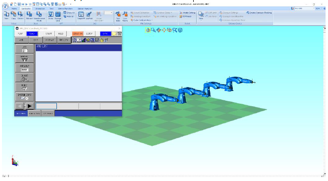
Procedure
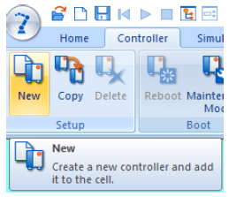
- Create a New Cell
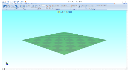
- On the Controller tab, select New in the Setup section
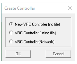
- Select New VRC Controller (no file). Click OK
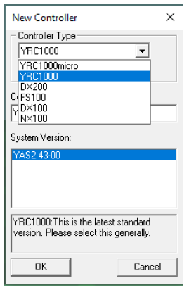
- Select Controller Type. Click OK
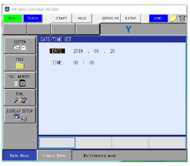
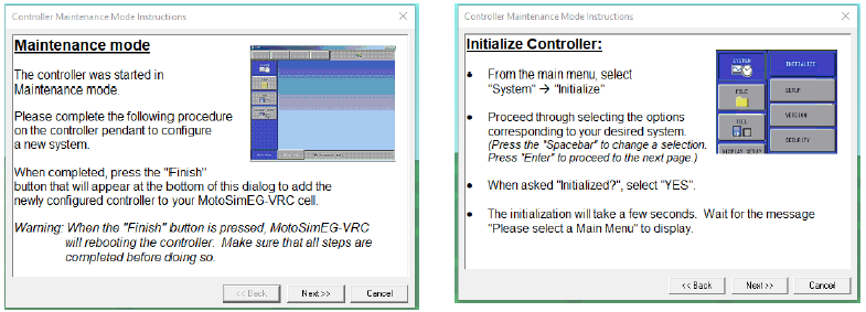
- Select Maintenance Mode Execute
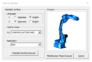
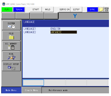
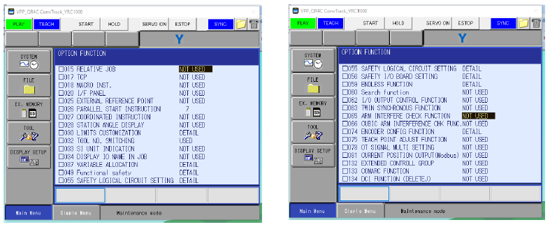
- On virtual pendant, select SYSTEM – INITIALIZE.
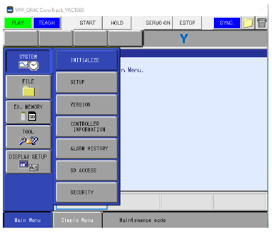
- Set Language. Press ENTER
- Set R1, R2, etc. as needed in DETAIL of each line using SELECT (refer to MotoSim EG-VRC manual sec. 15.9 for robot list). Press ENTER until you are past the CONNECT (STO) screen
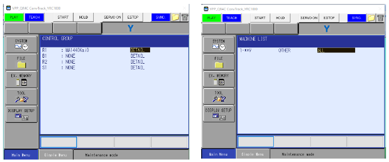
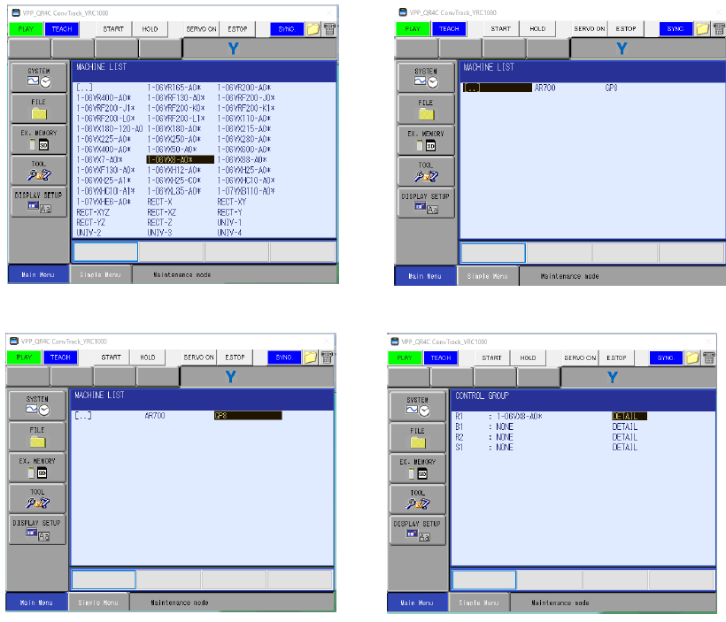
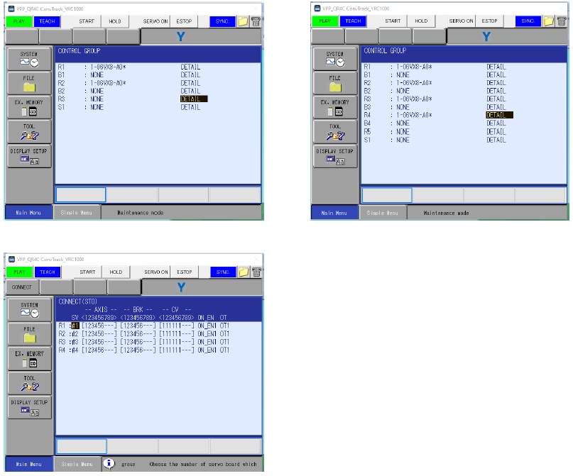
- Select APPLICATION (Application + must match robot count. If using 3 robots, application and ladder should be GENERAL + GENERAL + GENERAL. More than 4 read GENERAL * 5,6,7,8.) Press ENTER to confirm.
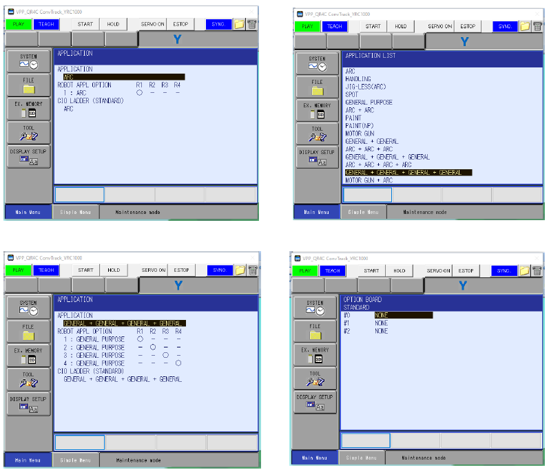
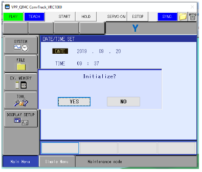
- Press ENTER until Initialize? Confirmation. Select YES.
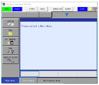
- Wait for Please select a Main Menu screen
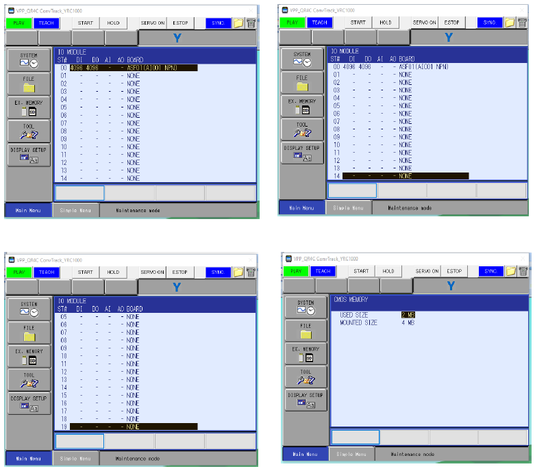
- Select SYSTEM- SETUP - OPTION FUNCTION to select robot options (such as Arm Interference, Relative Job, Coordinated Instruction, FSU, etc.).
* Robots in close proximity should have Arm Interference enabled and complete robot calibration(s)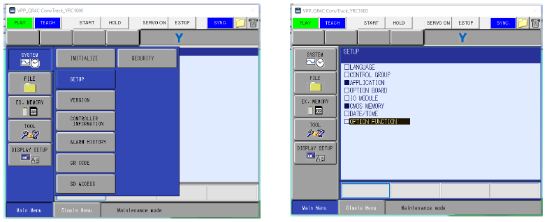
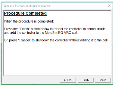
- Click Next on Controller Maintenance Mode Instructions window until the Procedure Completed window. Click Finish
- Click OK on Robot Settings window
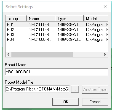
- Robots will automatically space 1M. Position robot(s) as needed with CAD Tree.
- Save
TOOLS REQUIRED
Computer system
MATERIAL REQUIRED
Simulation data/models
EQUIPMENT REQUIRED
Simulation software (MotoSim EG-VRC)
SEQUENCE OF OPERATION
PRECAUTIONS
- Ensure correct model selection
- Check program before running
- Avoid wrong command sequence
- Maintain proper path planning
- Verify gripper operation
.png)


Comments
Post a Comment